The Scientist and Engineer's Guide to
Digital Signal Processing
By Steven W. Smith, Ph.D.
Book Search

Table of contents
- 1: The Breadth and Depth of DSP
- 2: Statistics, Probability and Noise
- 3: ADC and DAC
- 4: DSP Software
- 5: Linear Systems
- 6: Convolution
- 7: Properties of Convolution
- 8: The Discrete Fourier Transform
- 9: Applications of the DFT
- 10: Fourier Transform Properties
- 11: Fourier Transform Pairs
- 12: The Fast Fourier Transform
- 13: Continuous Signal Processing
- 14: Introduction to Digital Filters
- 15: Moving Average Filters
- 16: Windowed-Sinc Filters
- 17: Custom Filters
- 18: FFT Convolution
- 19: Recursive Filters
- 20: Chebyshev Filters
- 21: Filter Comparison
- 22: Audio Processing
- 23: Image Formation & Display
- 24: Linear Image Processing
- 25: Special Imaging Techniques
- 26: Neural Networks (and more!)
- 27: Data Compression
- 28: Digital Signal Processors
- 29: Getting Started with DSPs
- 30: Complex Numbers
- 31: The Complex Fourier Transform
- 32: The Laplace Transform
- 33: The z-Transform
- 34: Explaining Benford's Law
How to order your own hardcover copy
Wouldn't you rather have a bound book instead of 640 loose pages?Your laser printer will thank you!
Order from Amazon.com.
Chapter 8: The Discrete Fourier Transform
The sine and cosine waves used in the DFT are commonly called the DFT basis functions. In other words, the output of the DFT is a set of numbers that represent amplitudes. The basis functions are a set of sine and cosine waves with unity amplitude. If you assign each amplitude (the frequency domain) to the proper sine or cosine wave (the basis functions), the result is a set of scaled sine and cosine waves that can be added to form the time domain signal.
The DFT basis functions are generated from the equations:
where: ck[ ] is the cosine wave for the amplitude held in ReX[k], and sk[ ] is the sine wave for the amplitude held in ImX[k]. For example, Fig. 8-5 shows some of the 17 sine and 17 cosine waves used in an N = 32 point DFT. Since these sinusoids add to form the input signal, they must be the same length as the input signal. In this case, each has 32 points running from i = 0 to 31. The parameter, k, sets the frequency of each sinusoid. In particular, c1[ ] is the cosine wave that makes one complete cycle in N points, c5[ ] is the cosine wave that makes five complete cycles in N points, etc. This is an important concept in understanding the basis functions; the frequency parameter, k, is equal to the number of complete cycles that occur over the N points of the signal.
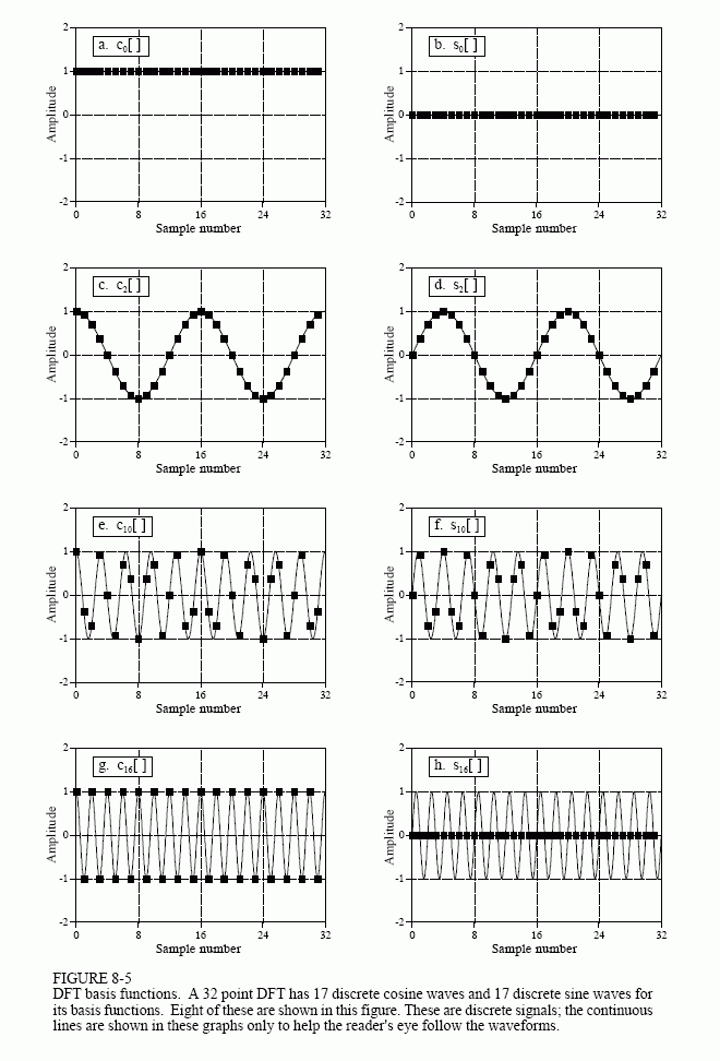
Let's look at several of these basis functions in detail. Figure (a) shows the cosine wave c0[ ]. This is a cosine wave of zero frequency, which is a constant value of one. This means that ReX[0] holds the average value of all the points in the time domain signal. In electronics, it would be said that ReX[0] holds the DC offset. The sine wave of zero frequency, s0[ ], is shown in (b), a signal composed of all zeros. Since this can not affect the time domain signal being synthesized, the value of ImX[0] is irrelevant, and always set to zero. More about this shortly.
Figures (c) & (d) show c2[ ] & s2[ ], the sinusoids that complete two cycles in the N points. These correspond to ReX[2] & ImX[2], respectively. Likewise, (e) & (f) show c10[ ] & s10[ ], the sinusoids that complete ten cycles in the N points. These sinusoids correspond to the amplitudes held in ReX[10] & ImX[10]. The problem is, the samples in (e) and (f) no longer look like sine and cosine waves. If the continuous curves were not present in these graphs, you would have a difficult time even detecting thepattern of the waveforms. This may make you a little uneasy, but don't worry about it. From a mathematical point of view, these samples do form discrete sinusoids, even if your eye cannot follow the pattern.
The highest frequencies in the basis functions are shown in (g) and (h). These are cN/2[ ] & sN/2[ ] , or in this example, c16[ ] & s16[ ]. The discrete cosine wave alternates in value between 1 and -1, which can be interpreted as sampling a continuous sinusoid at the peaks. In contrast, the discrete sine wave contains all zeros, resulting from sampling at the zero crossings. This makes the value of ImX[N/2] the same as ImX[0], always equal to zero, and not affecting the synthesis of the time domain signal.
Here's a puzzle: If there are N samples entering the DFT, and N+2 samples exiting, where did the extra information come from? The answer: two of the output samples contain no information, allowing the other N samples to be fully independent. As you might have guessed, the points that carry no information are ImX[0] and ImX[N/2], the samples that always have a value of zero.